
In a Boeing 737 NG cockpit a number of concentric shaft rotary encoder / band switch combinations are found, e.g. the Heading / Bank Angle selection combination in the MCP and the MINS and BARO combinations in the EFIS panel.
One way to build this combination is to drill a hole completely through the shaft and the body of a band switch so that a smaller shaft can go through it that is connected to the axis of a rotary encoder behind the band switch.
I used band switches of brand Alpha, similar to this one. If you buy them make sure that the axis is a fully round (not D-shape) plastic, 6 mm diameter; the knob mentioned below below only fits on a knurled axis, which is 6 mm instead of 6.35 mm.
The used rotary encoders are similar to this one, the shop where I bought my ones unfortunately doesn’t sell them anymore but there are many other shops selling the same ones.
Drilling this hole is a precision job, especially if the band switch shaft has 6 mm diameter and an inner shaft of 4 mm is used so that a knob with 4 mm hole exactly fits. This knob fits exactly in this bigger knob for the outer shaft.
For the inner shaft a 4 mm brass rod from a DIY shop is used.
With inspiration of a YouTube video I found the following way which appeared to be not as difficult as I expected. Using the described method I modified a total of 5 band switches in approximately 1 hour.
Needed are a drilling stand, an extra drill chuck (which came with my hammer drill) and a vise. I used a piece of the brass rod to align the drill and the extra chuck:

The first attempt resulted in this:

I was a bit puzzled where the part of the spring came from, so I opened the band switch to investigate.


The spring that pushes two metal balls in the serrated body of the switch to make it click runs straight through the shaft, so if you drill through the shaft without removing the spring first you run into trouble. But it appeared quite easy to open the switch, you only have to be careful when pulling the shaft out otherwise the two metal balls will fly away.

With the shaft removed, it’s much easier to drill the hole, because the internal end of the shaft has a center hole which makes it easy to center the drill.
But before drilling the shaft, first drill the hole in the switch body, because a massive shaft is less fragile when clamped in the chuck.

Next drill the hole in the shaft. Be careful not to damage the slider contacts.

I managed to drill a hole of 4.5 mm trough the 6 mm shaft, but better have a couple of reserve band switches available, because it requires a bit of practice to get the hole also exactly centered at the other end of the shaft.
Switches with knurled shaft are a bit thinner than non-knurled ones, so the latter are a bit easier, but the knob for the outer axis mentioned above only fits on the knurled axis.


Next the spring was cut in two pieces and the 4 mm brass rod inserted as a stop in the middle for the two spring pieces.

Putting the two balls back in place is a tricky job, but there is a small opening in the switch body that makes it easier: rotate the axis so that this opening exactly aligns with the hole for the spring, place the spring and first ball and rotate the axis to the other spring hole to place the second spring and ball.
Next pull the shaft completely towards the top of the switch body.


Now the switch body can be closed again.


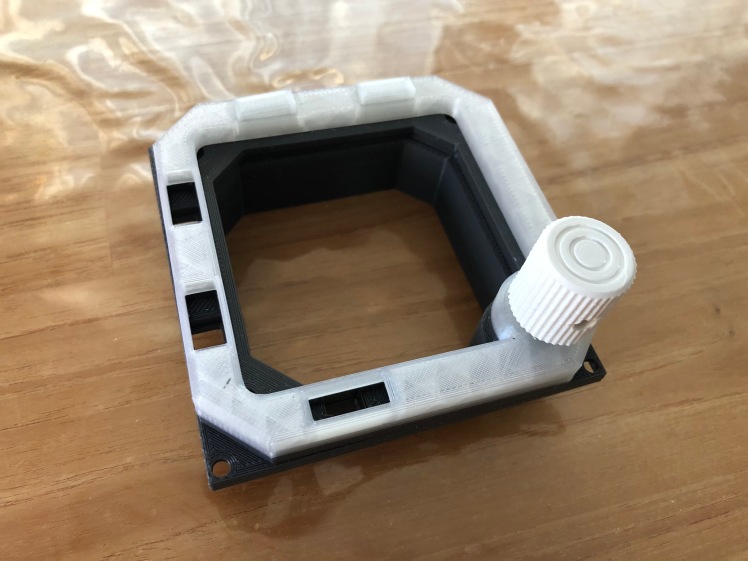
This was the first and most difficult part, next I have designed a 3D printed frame (STL format) to connect the rotary encoder and the band switch together and a small cylinder (STL format) to connect the 4 mm brass rod with the rotary encoder axis.


Very, very cool. You just gave me a reason to get a 3D printer. Did you do this because you couldn’t find any concentric rotary switches, or just none that suited your needs? I’m interested in my own build and not sure where to look for parts like this.
LikeLiked by 1 person
Hi Anthony,

Note that the one above isn’t a dual concentric rotary switch: it’s a band switch (with a number of fixed positions) combined with a rotary encoder (which only gives pulses, but doesn’t have a fixed position, i.e. when you start the simulator you don’t know in which position it is).
Elsewhere in this blog I also built my own dual concentric rotary encoder, mainly because the ones that I found in that time where expensive (20 pounds + additional knob set).
Meanwhile however I have found more affordable ones: 9.20 euro and during sale even 7.80 a piece: https://a.aliexpress.com/_Ukict
That’s still a lot more expensive than my DIY one, but this one works smoother.
But then the challenge is to find a concentric knob set for the specific axis dimensions.
And that’s what a 3D printer is very handy for, because you can create your own knobs. I’m currently designing knobs for this purchased dual encoder, but unfortunately haven’t found the exact dimensions of the real knobs yet, so for the moment I designed something that comes close (for the top knob I’m printing a new conic design right now):
But you can do a lot of other nice things, e.g. I’m also working on a frame with switches and rotary encoder for the MIP standby HSI device (sneak preview 😉
I bought my Creality CR-10S 300 printer (not the Pro) about 4 weeks ago and it has not been idle since that moment 😉
Two of my colleagues had this model and recommended it to me and I haven’t regretted a moment.
The Pro is newer and has the controller embedded, but I read in reviews that the auto leveling is a pain.
With my CR10-S I have only levelled manually once and so far there has been no need to redo it yet.
When I’m happy with the results I’ll post the design of these knobs for free download at this blog.
LikeLike